| Home > Grid Automation > Asset Monitoring > Legacy Primary Asset Monitoring | |||||||||||||||||||
|
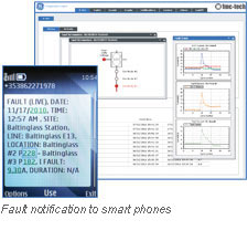
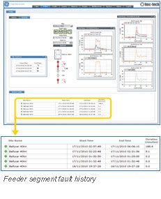
Fault Detection and Analysis
Dynamic Line Rating
|
||||||||||||||||||
|
Overview
The Multilin Intelligent Line Monitoring System is an end-to-end line monitoring solution with advanced analytics that provides actionable intelligence to distribution utilities to improve the reliability and efficiency of their networks.
Key Benefits
Fault Detection, Location and Analysis Application (X-NET Software)
Dynamic Line Rating Application (T-NET Software)
Advanced Overhead Line Sensing

As part of the Intelligent Line Monitoring System, the sensors play a key role in providing visibility along the distribution network. The sensor measures and records the current, both amplitude and phase, at 32 samples per cycle, and communicates to the SNG via an on-board 2.4 GHz radio. The sensor is configured to detect fault conditions facilitating rapid identification and notification. In addition, the sensors can be configured to provide periodic measurements to facilitate improved situational awareness and operations. The sensor can be supplied with an optional temperature probe on a flying lead that measures the surface temperature of the conductor facilitating dynamic line rating analysis and conductor temperature monitoring. Installation of the Multilin FMC-T6 line sensor can be completed in just minutes on a live line using either hot-stick or hot-glove. Sensors can be installed on 480V to 140kV feeders and will sit on conductors ranging from 10 mm to 28 mm in diameter. The sensor commences operation as soon as it is closed around the conductor and a small flashing LED mounted in the sensor housing indicates that it is operational. The magnetic field of the line provides the power for the sensor and also charges a 48 hour battery back-up that keeps the sensor operational in the event of an outage. Time Synchronized Communications with the Sensor Network Gateway
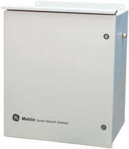
As part of the Intelligent Line Monitoring System, the Sensor Network Gateway (SNG) plays a vital role in ensuring connectivity between the applications and the field, providing visibility along the distribution network. The SNG provides a communications gateway for distribution network and weather information that is critical for advanced applications such as fault location and analysis, dynamic line rating, maintenance planning and feeder visualization. Alternatively the SNG delivers measured data in DNP3 format to head end systems. The SNG provides two way communications to the line sensors by 2.4 GHz radio. The SNG receives weather data from to the weather station and/or ultrasonic anemometer by a hardwired link. The SNG also records voltage, both amplitude and phase, at 32 samples per cycle via substation or feeder voltage transformers (VT’s). The SNG is equipped with several backhaul options for communicating with the advanced applications including 2G/3G GRPS/UMTS as well as serial and Ethernet communication ports. Each SNG is equipped with a GPS transceiver that synchronizes the entire system, enabling GE’s advanced analytics. The SNG is versatile and can be installed along the distribution feeder communicating with the line sensors or in a substation for voltage monitoring. Typical feeder installation scenarios include a single SNG with three sensors (one sensor per phase) or a single SNG with six sensors located at a branch port or feeder tap enabling it to effectively monitor two circuits at one site. Radio range between the line sensors and the SNG is typically 30 meters/100 feet, and the SNG is normally mounted on the same pole or structure underneath the sensors. The SNG is a low power device and can be powered by a solar panel or by a 100V/250V AC power supply. Application Data Specifications
System Management Specifications
Software Specifications
Certifications
Type Tests
Feeder Visualization Application
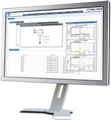
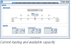
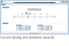
In addition to delivering measured data in DNP3 format, GE's feeder visualization application increases situational awareness along distribution feeders and enables utilities to operate and respond based on prevailing conditions, not static or seasonal estimates. This application provides actionable information enabling utilities to:
GE's Intelligent Line Monitoring system is time synchronized enabling data from multiple locations along the distribution network to be aligned to within 40µS. Accurate time synchronization enables the delivery of positive, negative and zero sequence currents at each measuring location along with substation voltage. |
|||||||||||||||||||
Copyright © GE Grid Solutions LLC, 2024