


|
Multilin D400 - Legacy
Advanced Substation Gateway
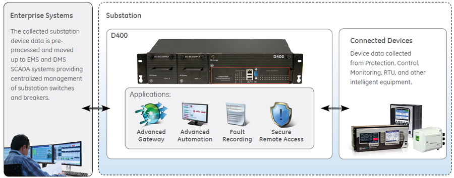
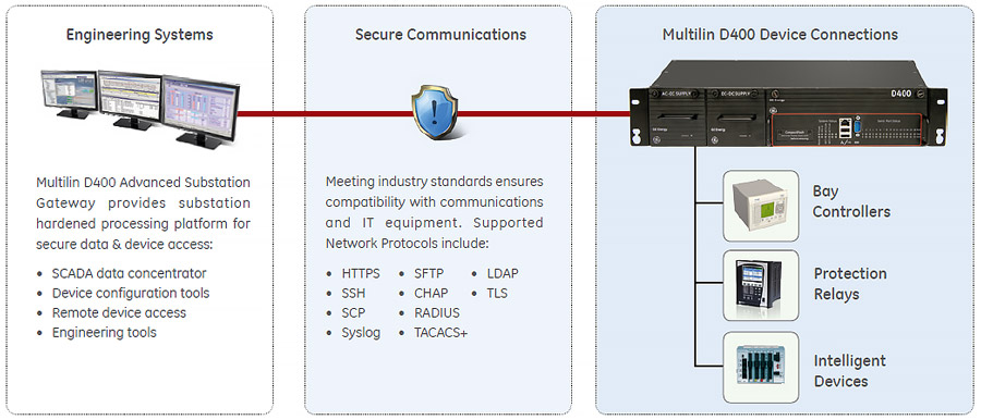
Manufacturing for the D400 has been discontinued. As an alternative, please refer to the G100 or G500. Manufacturing for the DMC-490 has been discontinued. As an alternative, please refer to the GridNodeMicroGrid solution. GE's Multilin™ D400 is a secure, substation-hardened gateway that collects metering, status, event, and fault report data from serial or LAN based Intelligent substation devices. The D400 summarizes data from the substation devices and makes it available locally/remotely through a standard secure web browser (HTTPS). The Multilin D400 supports serial and/or LAN connections to SCADA masters. TCP/IP network connections are supported over the built-in Ethernet and the modem interface. Key benefits
Applications
|
![]() Advanced Gateway
Advanced Gateway
The D400 collects data from substation protection, control, monitoring, RTU, and intelligent devices, pre-processes the data and moves it up to EMS and DMS SCADA systems providing centralized substation management.
![]() Advanced Automation
Advanced Automation
The D400 provides the computing platform necessary to automate substation procedures, such that intricate processes are carried out safely and efficiently by creating custom automation programs using IEC 61131 compliant tools, and perform basic math functions on data points using the built-in Calculator tool.
![]() Fault Recording/Data Logging
Fault Recording/Data Logging
Using pass-through connections, users can extract valuable non-operational data such as digital fault recording (DFR) records and event files. The user can also access the historical log files and upload the archived data for trending and analysis.
![]() Secure Remote Access
Secure Remote Access
The D400 allows maintenance and relay engineers to securely access substation devices, locally or remotely, through advanced visualizations and communication tools, increasing productivity.
Hardware
The D400 is built on a flexible, high performance, expandable disk-less and fan-less platform that is powered by a 1.0Ghz processor.
Two Ethernet networks are supported with separate multiport switches. An IRIG-B format time protocol input/distribution module is also supported. Isolated serial port media is selected for each pair of ports.
Redundant power supplies
The D400 has dual redundant, hot swappable power supplies, ensuring continuous uptime. Each power supply can be connected to a different source. As an example Power supply 1 can be connected to Mains, while power supply 2 is connected to the battery system. Power Supply Health Monitoring raises a SCADA point alarm when either power supply fails. This allows an alarm to be transmitted to the EMS /OMS or DMS system, where a field personnel can be dispatched to replace the failed supply, all without service disruption.
Time Sync Support
The D400 has extensive support for various time sync methodologies and will accept time sync signals from SNTP/NTP Servers, IRIG-B (un-modulated/modulated), and SCADA protocols. The D400 can also distribute this time sync information through its built-in IRIG-B distribution interface, SCADA protocols, and/or through the RS232 ports directly.
Advanced Gateway Connectivity
Data collection, concentration and visualization
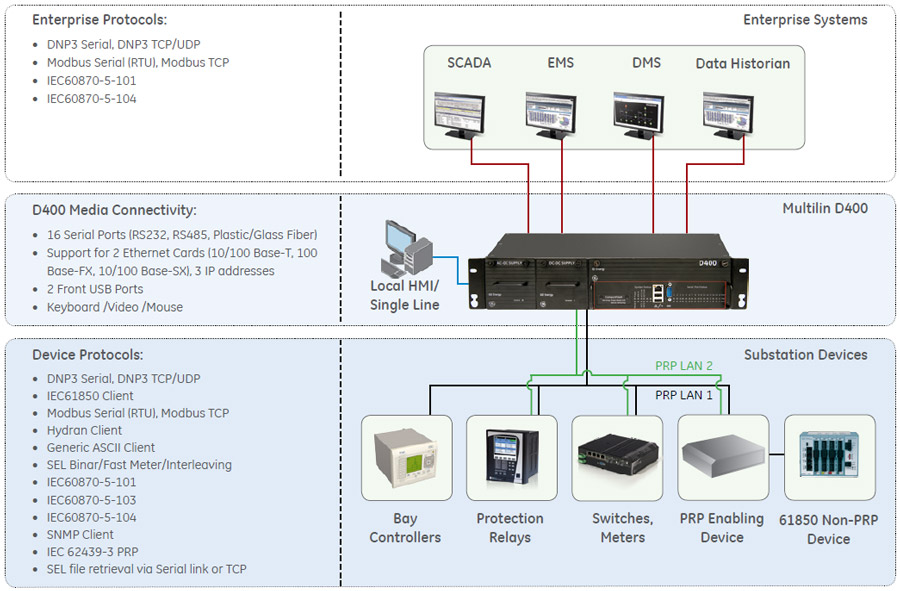
The D400 Substation Data Manager, when operating as a SCADA host, collects, filters, and sorts data from a wide range of intelligent devices (RTUs, relays, meters) in the substation and preserves original data time stamp for accurate sequence of event. Data can be presented to multiple SCADA hosts. The D400 comes with a built-in suite of protocols and security applications to facilitate communication with various substation devices and SCADA hosts, including:
IEC 61850 Gateway
The IEC 16850 Client application allows the D400 to act as a powerful IEC 61850 data concentrator. The D400 also includes valuable features such as Dynamic Data Sets, Buffered Control blocks, Enhanced Security controls.
Device Redundancy (Hybrid Model)
Dual D400 units can be deployed creating a redundant system where accumulators, SOE logs, and configurations are automatically synchronized between the two systems. Serial communication links are automatically switched between the units based on system health.
The D400 100Base-FX redundant Ethernet card enables automatic switchover between two sets of Ethernet switches ensuring there is no single point of failure in the system.
D400 now supports PRP by actively communicating on two physical Ethernet ports connected to two independent network LANs simultaneously. PRP allows systems to overcome any single network failure without affecting the data transmission. It provides seamless failover redundancy.
The D400 supports three modes of operation:
The D400 can be configured to operate in one mode at any given time.
Built in Media Conversion
The D400 supports various communication media types—Serial: RS-232, RS-485, Glass Fiber, and Plastic Fiber; and Ethernet: 10/100Base-T, 10Base-FL, and 100Base-FX. Hot swappable communications modules eliminate the need for dongle type media converters used to convert to glass or plastic fiber, reducing total cost of deployment.
Advanced Automation
The D400 acts as the centralized, rugged computing platform in advanced Automation systems. Using the calculator tool and/or GE's programmable logic (LogicLinx), users can create custom automation programs for a variety of applications such as:
HMI, one-line viewer & Annunciator
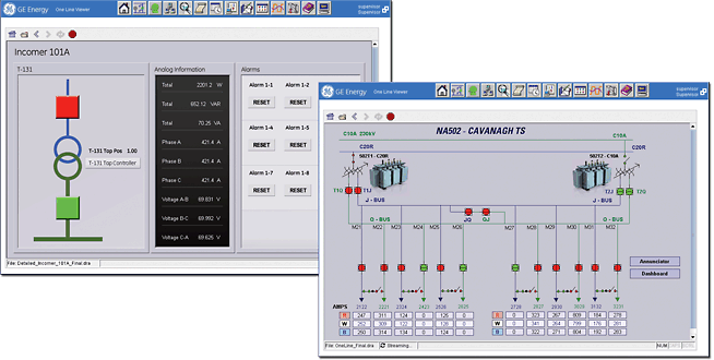
The D400 supports a web based HMI/Annunciator feature, that is accessible remotely, using a standard Internet browser or locally, through a direct connection to the unit. Users have access to all data points in the systems, alarm screens, communications status screens ,and dynamic One-Line diagrams, all through the secure web interface.
The web based HMI supports the following security features to ensure secure remote or local access:
Web based HMI/Annunciator feature, that is accessible using a standard Internet browser or through a VGA monitor and USB keyboard/mouse attached directly to the unit.
Mathematical Control Logic
Using the Calculator tool, users can create advanced solutions that group, manage and control points to produce the required automation results. The calculator tool can perform mathematical, logical, or timer based operations on any data points stored in the D400. Using a graphical interface, users can define logical expressions using mathematical functions such as; addition, multiplication, logarithm, greater than, less than, as well as other boolean functions.
Programmable Logic (LogicLinx)
For more advanced applications, programmable logic (LogicLinx) software provides PLC functionality on the D400 platform. LogicLinx offers textual and graphical languages as defined in the IEC 61131-3 standard for PLC programming environments, including Sequential Functions Chart, Instruction List, Structured Text, Ladder Diagram and Function Block Diagram. In addition, a wide range of arithmetic, Boolean and logical operations are supported.
Fault Recording/Data Logging
Data Logger
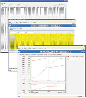
The Analog Data Logger provides a variety of means to monitor and record any analog input point value changes into data files that can be retrieved by the user. A variety of recording methodologies are supported including, Continuous (all changes), Periodic, Time weighted, Out of range and Triggered by a digital input point.
Trend Viewer
All data recorded by the Analog/Digital Data Logger can be viewed by the Digital event recorder using the built in web-based Trend Viewer. Users can select the range of data to be used by time and date, alternately a real time streaming view can be displayed. Up to 8 data points (pens) can be displayed on a single view and support for curve fitting is available.
Data Base Exporter
The Database Exporter tool allows users to save Analog Data Logger and Digital event recorder points from the D400 to your local PC, using the WEB interface, in comma-separated values (CSV) format.
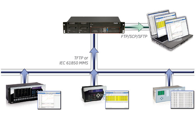
Automatic Record Retrieval
The Automated Record Retrieval Manager (ARRM) retrieves and stores record files from devices connected to the D400. ARRM uses the Distributed Network Protocol (DNP) and the IEC 61850 protocol to communicate with a variety of devices, and uses the Trivial File Transfer Protocol (TFTP) or MMS to transmit the files from the IED to the device over a Local Area Network (LAN) or serial connection.
You can also retrieve downloaded records from the D400 using any FTP/SCP/SFTP client as needed or on a scheduled basis.
ARRM supports a configurable interval for polling connected devices. This can be activated or deactivated through the runtime viewer display screen.
The connection status of the devices, in addition to the data retrieved from the IEDs can also be displayed or made available directly to the Tarigma Grid Enterprise Manager (GEM) software.
Parallel Redundancy Protocol
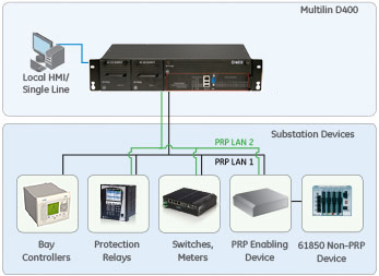
IEC 62439-3 (Edition 2), Parallel Redundancy Protocol
Substation LAN redundancy has been traditionally accomplished by reconfiguring the active network topology in case of failure. Regardless of the type of LAN architecture (tree, mesh, etc.), reconfiguring the active LAN requires time to switchover, during which the LAN is unavailable.
Parallel Redundancy Protocol is an IEC 62439-3 data communication network standard which is often used to overcome single network failure without affecting the data transmission. PRP is independent of the communication protocols and provides no packet loss (“zero recovery time”) availability by using connected nodes which transmit and receive over two independent network active paths. Under PRP, each network node has two Ethernet ports attached to two different local area networks, using standard bridges, and similar topology.
Existing D400 systems with 1 GHz or newer CPU can be upgraded via firmware in order to enable the Parallel Redundancy Protocol. The D400 can communicate simultaneously to devices connected to a common network, carrying mixed traffic: single LAN, legacy redundant or dual LAN, and PRP. This aids in implementing PRP in brown field installations, taking advantage of possible spare ports on existing managed switches LAN infrastructure. Additional LAN switches may be added as needed.
Analog Report Generation
In addition to the data logging capability within the D400, users can configure the D400 to record and generate online and offline reports from operational and non-operation analog data. While online reports can be retrieved instantly and are an extension of the data logger periodic reports, offline reports can be retrieved daily, weekly or monthly.
Offline Reports:
Offline Reports
Report Configuration Steps
Types of Offline Reports and Key Parameters:
| report type | report duration | start time alignment | logging interval | logging alignment |
|---|---|---|---|---|
| Shift | Configurable 4, 6, 8 or 12 hours |
Configurable 0-23 hour |
Configurable 15, 30, 60 minutes |
Configurable 00:00, 00:15, 00:30 or 00:45 |
| Daily | Fixed 1 day |
Configurable 0-23 hour |
Configurable 15, 30, 60 min and 4, 6, 8 hours |
Configurable 00:00, 00:15, 00:30 or 00:45 |
| Weekly | Fixed 7 days |
Configurable 0-23 hour |
Configurable 12 and 24 hours | Configurable 0-23 hours |
| Monthly | Fixed 7 days |
Configurable 1-31 date |
Configurable 12 and 24 hours |
Configurable 0-23 hours |
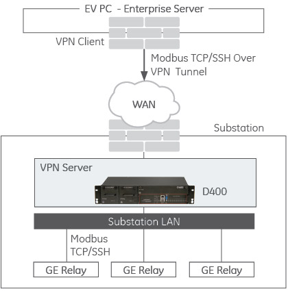
OpenVPN Architecture Example
Key features:
Secure Remote Access
D400 provides robust security environment, providing seamless integration with existing IT department policies. Role based Access Control, Secure Web Interface, Secure File Transfer, and extensive user activity logging provide a complete security toolkit required to achieve NERC-CIP compliance.
Non-operational Data
Using pass-through connections, the utility user can extract valuable non-operational data such as digital fault recording (DFR) records and event files. The user can also access the historical log files and upload the archived data for trending and analysis.
Pass-through/Terminal Server
A built-in terminal server emulator allows pass-through connections to be initiated to substation device (relay, meter, RTU or other device). Once the connection is established, the local event records can be uploaded from the substation devices and viewed remotely. Remote access can be secured with TLS or SSH.
Virtual Serial Ports
Virtual serial ports eliminate copper wire communications to feeder bays when a serial-only device is located in the bay. A small terminal server can be placed in the bay and connected to the Ethernet network, allowing all D400 serial client applications to connect directly to the serial device.
Role Based Access Control
Role Based Access Control is achieved using LDAP, TACACS+, RADIUS or the D400’s internal database; ensuring only authenticated and authorized users gain access the system. When using LDAP, TACACS+, or RADIUS, revoking user privileges, system wide, is as simple as updating the centralized user database.
Network security protocols:
Built-in Firewall
Multilin D400 is equipped with a built-in firewall for enhanced gateway cyber security. D400's firewall is designed to drop unsolicited or invalid routed packages. The firewall is preconfigured to block outbound traffic on external interfaces and inbound traffic on both internal and external interfaces. The D400 automatically generates rules allowing inbound traffic on internal interfaces for all configured services. The rules are user configurable for inbound/outbound traffic customization.
HMI, One Line & Annunciator
The Multilin D400 supports a web based HMI/ Annunciator feature, that is accessible using a standard Internet browser or through a VGA monitor and USB keyboard/mouse attached directly to the unit. Users have access to all data points in the systems, alarm screens, communications status screens and dynamic one line diagrams, all through the secure web interface.
The D400's web based HMI supports the following security features to ensure secure remote or local access:
